Drawing Tools
Overview
Reference material for the Drawing Tools tool/feature in ATAK, sourced from the official ATAK 5.7 Software User Manual (chapter 17, "Drawing Tools").
Manual Reference
Drawing Tools provides the ability to create different shapes and/or telestrate on the map. Available shapes include, circle, ellipse, rectangle, free form and telestrate. Create a shape to access the radial menu option associated with each shape type.


The Delete, Fine Adjust, R&B Line and Details radial options behave in the same manner as other map objects.
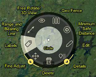
The Labels option toggles on/off a label associated with the shape displaying the shape’s dimensions or name. The Free Rotate / 3D View (eye icon) radial option allows map rotation and to view in 3D mode. A yellow eye will appear in the upper left corner and as the map is rotated, the degrees of rotation are displayed and updated. Tapping the yellow eye again will turn the feature off.
The Geo Fence Tool creates a virtual fence that triggers entry/exit notifications based on its assigned parameters. The Edit option can be used to re-adjust and make additional changes to the shape, as needed. In addition to the standard configuration options that are present in the Details window, the area of the shape is calculated and displayed here as well.
Free Rotate/3D View provides display options. All shape types with height can be rendered as 3-dimensional objects when the map is in 3D Mode.
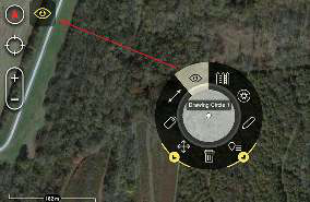

Create a Shape - Circle
To add a Circle, select the Circle icon, select a location to place the center point and tap another location for the radius. Select the circle and select Details on the radial menu to change the name, radius, number of rings, color, opacity, line thickness, line style, add a remark, add an attachment or to send/broadcast the circle information to others.

All dimensions (radius, area, circumference and height) can be manually adjusted in the Details allowing for precise shape placement on the map. Label visibility and Center point visibility can also be controlled from the Details. Selecting any point of the circle on the map, will open the circle radial menu.
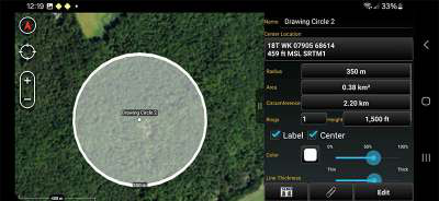
To edit the circle, select Edit from the Details window. Long press the center point to move the circle or long press the edge to resize. Select Undo to reverse changes or select End Editing to save the changes.
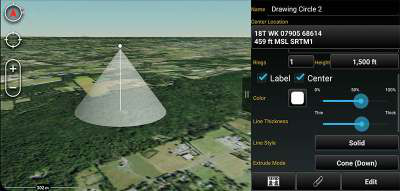
Extrude Mode (circle only) can change a circle with a height to a Cone (Down), Cone (Up), Cylinder, Dome, or Sphere. To enable this feature, place the circle and then define a height for the circle in the details. Once the height has been defined, the Extrude Mode field becomes active. Select from the list of shapes available. Placing the device into 3D mode, displays the circle with the selected extrusion.

Create a Shape - Ellipse
To add an Ellipse, select the Ellipse icon, select a location to place the first corner, select another location for the second corner which sets the edge, and finally select a third location to establish depth.

Select the ellipse and select Details on the radial menu to change the name, display the label or center point, color, opacity, line thickness, line style, add a remark, add an attachment or to send/broadcast the circle information to others.
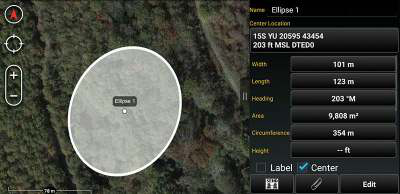
All dimensions (width, length, heading, area, circumference and height) can be manually adjusted in the Details, allowing for precise shape placement on the map. Label visibility and center point visibility can also be controlled from the Details. To edit the ellipse, select Edit from the Details window. Drag or long press the markers to edit the ellipse on the map. Select Undo to reverse changes or select End Editing to save the changes.
Create a Shape - Rectangle
To add a Rectangle, select the Rectangle icon, then select a location to place the first corner, select another location to add a parallel corner and then select a third location to indicate the desired depth of the rectangle.

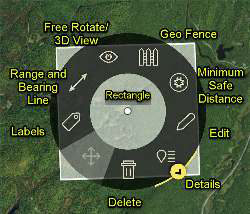
Selecting any point of the rectangle on the map will open the rectangle radial. Note that Fine Adjust is not active for this shape. To edit the rectangle, select the Edit icon. Drag a corner or side of the rectangle, or long press a mid- point or vertex, to move the selected side. The rectangle can be rotated if one of the four mid-points is held and dragged. Select Undo to reverse changes or select End Editing to save the changes.
Select the rectangle and select Details on the radial menu to change the name, color, opacity, line thickness, line style, show labels, show center point, show tactical overlays, add a remark or send/ broadcast the rectangle information to others. All dimensions (width, length, area, perimeter and height) can be manually adjusted in the Details allowing for precise shape placement on the map. Label visibility and center point visibility can also be controlled from the Details.
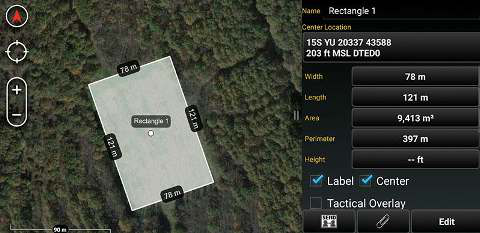
Selecting the Tactical Overlay option will allow the user to add tactical color coding to a structure being outlined, establishing a common set of terms for operational coordination. The white side of the rectangle represents the front, while black represents the back of a structure. The green side of the structure appears clockwise from the front (white), while the red side appears counterclockwise.
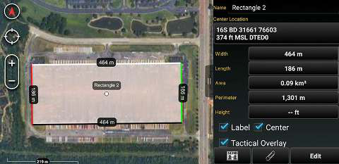
The first point during placement should be the left front corner of the structure (white/green corner), while the second point should be the right front corner of the structure (white/red corner) and the third point should be the back. Create the rectangle and when the Details menu is displayed, select the Tactical Overlay checkbox to turn on the color coding.
Create a Shape - Free Form
Free Form
To add a Free Form shape (i.e., a polyline or polygon) on the map, select the Free Form icon and then select a location to place the first vertex for the shape; continue to tap to add vertices. Select the initial vertex to close the shape or select End Shape to form an open shape. Select the Undo button to remove the links in sequence.

Select the free form on the map and select Details on the radial menu to change the name of the shape, coordinate center point, coordinate units, color, opacity, line thickness, line style, add height, add a remark or send/broadcast the shape information to others.
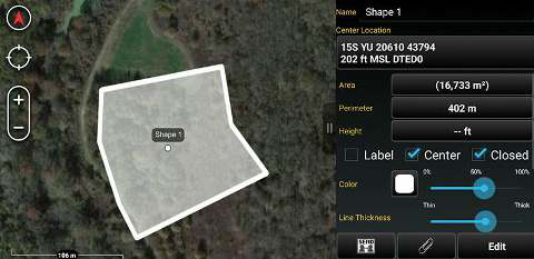
Checking the Show Labels box will display the name of the shape on the perimeter. Checking the Center box will unhide/hide the center point and center point label. Checking the Closed box will display a closed shape versus an open shape on the map. An open shape’s center point cannot be changed. On a free form line, the Details pane displays the start point and end point of the line. Start Point and End Points can be precisely adjusted from the Details pane.
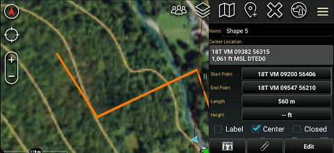
Selecting the shape on the map will open the free form radial. Note that Fine Adjust is not active for this shape. To edit the shape, select the Edit icon on the radial. Drag a vertex of the shape or long press a line to add a vertex. Select Undo to reverse changes or select End Editing to save the changes.
Telestrate
Select the Telestrate icon to access the Telestrate toolbar. Selecting the Telestrate icon enables and disables map scrolling by turning telestration on or off. When Telestrate is toggled on, the user is able to free form draw manually or with a stylus.

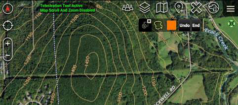
Select Undo to remove the most recent activity. Selecting End, ends the current telestration session saving all activity as a single multi-polyline and returns the user to the main Drawing Tools menu.
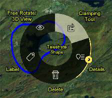
Selecting a telestration on the map will open the radial menu. Select Details on the radial menu to change the name, add a height, change line colors, delete lines or add lines, adjust line thickness, select line style, add remarks or send/broadcast to others. In addition to the Details, Delete, Label and Free Rotate/3D View, the Clamping Tool is available. Select the Clamp radial option to bind the map item to the map’s surface.
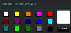
Selecting the Color Selection icon will open the Choose Telestration Color menu. Choose a provided color or select Custom to customize a color.
Briefing Graphics and Tactical Symbols
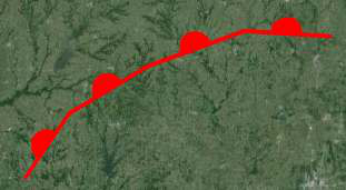
Depending on the specific symbol type selected, the procedure for placing a symbol or graphic shape will be the same as for an ordinary Drawing Tools shape (e.g., free form shape, rectangle, or circle etc.). The shape will draw on the map according to the selected type instead of as an ordinary free form shape. The symbol or graphic type is listed in the shape’s Details panel, where it can also be changed or cleared.

Minimum Safe Distance
Select the Minimum Safe Distance (MSD) radial option to create a zone around a shape that has been previously placed on the map.

Use the Range field to specify the distance from the shape’s border that the zone will be created from. MSD color can be adjusted by selecting the color swatch and the visibility for the zone can be enabled by checking the Enabled checkbox.
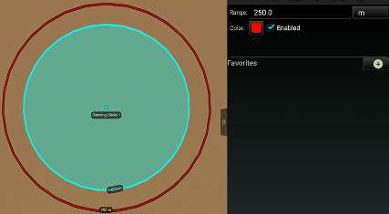

MSDs can also be created and saved to the Favorites section by selecting the +. These favorites are shared between all shape types that support this feature. Select an MSD from the Favorites section to quickly enable it.
Source
ATAK 5.7 Software User Manual, 13 March 2026 (Unclassified), pages 64–70.