Drawing Tools
Overview
Reference material for Drawing Tools in WinTAK, sourced from the official WinTAK 5.7 Software User Manual (26 March 2026).
Manual Reference

Drawing Tools allow for the creation of different shapes on the map. Select the Drawing Tools icon to reveal the list of tools. Options include: polyline, rectangle, circle, ellipse, freeform, telestration and manual. The manual option provides an additional way to create a polyline using specific coordinates. After a closed shape has been created, a Geo Fence may be added. Geo Fenced areas can alert users when markers matching the parameters configured in the Geo Fence Tool enter or exit the defined area.
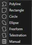
Create a Shape — Polyline

To create a polyline/polyshape, select Polyline and then a location on the map to place the first vertex of the shape. Continue to place vertices by selecting different map locations.
Select the Undo button to remove the last action in sequence. Close the shape by selecting the initial vertex or select End Shape to end with an open shape. Once the shape has been created, the Shape Details menu appears. Details that can be changed include: Name, Center Point Location, Elevation, Height, Color, Opacity, Line Style, and Remarks. After a shape has been created, select Send to send the shape to another user, select Attachment to attach a file(s) to the shape, or select Edit to make changes to the shape's position and size on the map.
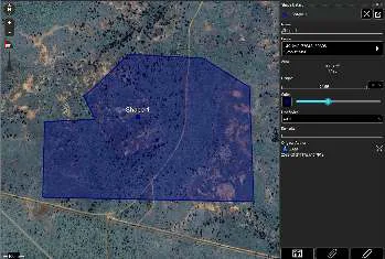
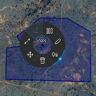
Select the shape on the map to open the shape's radial menu. Options available include: Delete, Fine Adjust, Range and Bearing (R&B) Line, Clamp, Geo Fence, Edit and Details (with quick send from sub-radial). While an option is toggled on, such as Clamp, its radial section will be highlighted blue. Select Edit on the radial menu to launch editing mode, which makes the vertices selectable/moveable.
Move a vertex to a new location by selecting, holding and dragging. Click a vertex to access a radial menu with options for Fine Adjust, Coordinate Entry, MGRS Entry, and Delete. Long press/right click on a line to add a vertex, which can then be moved to a new location. Select Undo to reverse changes in sequence. Select End Editing to save all changes and end edit mode. The entire shape can be moved by long pressing/right clicking on the shape center point and selecting a new location.
Create a Shape — Rectangle

To create a rectangle, select the Rectangle icon from the Drawing Tools menu. Select the location of the first corner on the map and then drag and release to position the opposite corner.
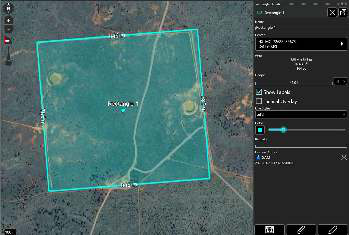
Once the rectangle has been created, the Rectangle Details menu appears. Details that can be changed include: Name, Center Point Location, Elevation, Height, Show Labels, Tactical Overlay, Line Style, Color, Opacity and Remarks. After a rectangle has been created, select Send to send the rectangle to another user, select Attachments (paperclip) to attach a file(s) to the rectangle, or select Edit (pencil) to make changes to the rectangle's position and size on the map.
Tactical Overlay
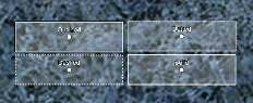
Select the Tactical Overlay option to enable tactical color coding for a structure being outlined. This can establish a common set of terms for operational coordination. The white side of the rectangle represents the front, while black represents the back of a structure. The green side of the structure appears clockwise from the front, while the red side appears counter-clockwise.
Create the rectangle and when the details menu is displayed, select the Tactical Overlay checkbox to apply the color coding. If the color coding is not correct, resize and rotate the rectangle to have the colors fall appropriately on the structure.
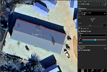
Select the rectangle on the map to open the rectangle's radial menu. Options available include: Delete, Fine Adjust, R&B Line, Clamp, Show Labels, Geo Fence, Edit and Details (with quick send from sub-radial). While an option is toggled on, such as Show Labels or Clamp, its radial section will be highlighted blue. Select the Edit icon on the radial menu to launch edit mode.
Move a corner to a new location by selecting, holding and dragging. Click a corner vertex to access a radial menu with options for Fine Adjust, Coordinate Entry, and MGRS Entry. Select, hold and drag + on a side to rotate the rectangle. Select Undo to reverse changes in sequence. Select End Editing to save all changes and end edit mode. The entire rectangle can be moved by long pressing/right clicking on the rectangle center point and selecting a new location.
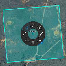
Create a Shape — Circle

To create a circle, select the Circle icon. Select a location on the map for the circle center and drag to determine the radius. Once the circle has been created, the Circle Details menu appears.
Details that can be changed include: Name, Center Location, Elevation, Radius, Number of Rings, Height, Color, Opacity, Line Style, and Remarks. Circles also support an extrusion mode when displayed in 3D, with Clamp turned off. Specify a height and the desired extrusion type (ConeDown, ConeUp, Cylinder, Dome or Sphere) and then shift into 3D to view the extrusion.
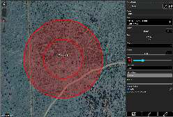
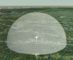
After the circle has been created, select Send to send the circle to another user, select Attachments (paperclip) to attach a file(s) to the circle, or select Edit (pencil) to make changes to the circle's position and size on the map.
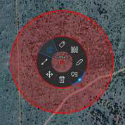
Select the circle on the map to open the circle's radial menu. Options available include: Delete, Fine Adjust, R&B Line, Clamp, Show Labels, Geo Fence, Edit and Details (with quick send from sub-radial). While an option is toggled on, such as Show Labels, its radial section will be highlighted blue. Select the Edit icon on the radial menu to launch edit mode. Move the circle center by selecting it and then a new location on the map for the circle to be placed.
Change the circle radius by selecting the circle edge and then a new location on the map for the radius. Select Undo to reverse changes in sequence. Select End Editing to save all changes and end edit mode. The entire circle can be moved by long pressing/right clicking on the circle center point and selecting a new location.
Create a Shape — Ellipse

To create an ellipse, select the Ellipse icon from the Drawing Tools menu. While the Ellipse Tool is active, click a location to place an edge and then adjust the shape of the ellipse by moving the mouse. Click again to confirm the shape of the ellipse.
Once the ellipse has been created, the Ellipse Details menu appears. Details that can be changed include: Name, Center Location, Elevation, Width, Length, Heading, Height, Color, Opacity, Line Style, and Remarks.
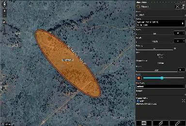
After the ellipse has been created, select Send to send the ellipse to another user, select Attachments (paperclip) to attach a file(s) to the ellipse, or select Edit (pencil) to make changes to the ellipse's position and size on the map.
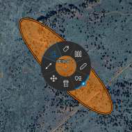
Select the ellipse on the map to reveal the ellipse's radial menu. Options available include: Delete, Fine Adjust, R&B Line, Clamp, Show Labels, Geo Fence, Edit and Details (with quick send from sub-radial). While an option is toggled on, such as Show Labels or Clamp, its radial section will be highlighted blue.
Select the Edit icon on the radial menu to launch edit mode. Move an edge to a new location by selecting, holding and dragging. Click an edge vertex to access a radial menu with options for Fine Adjust, Coordinate Entry, and MGRS Entry. Select Undo to reverse changes in sequence. Select End Editing to save all changes and end edit mode. The entire ellipse can be moved by long pressing/right clicking on the ellipse center point and selecting a new location.
Create a Shape — Freeform

Freeform shapes can be drawn on the map in one of two ways. To start a freeform shape, select the Freeform icon from the Drawing Tools drop-down. The user can either click the map, move the mouse to draw the shape and then click the map again to finish the shape, or left click + hold the mouse while drawing the freeform shape on the map and release to finish the shape.
Once the freeform shape has been created, the Shape Details will appear with options similar to that of the Polyline. The Name, Center Location, Height, Color, Opacity, Line Style, and Remarks can be edited.
Select Send to send the shape to another user, select Attachment to attach a file(s) to the shape, or select Edit to make changes to the shape's position and size on the map.
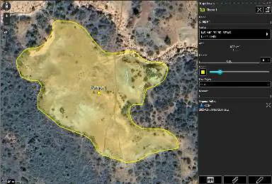
Select the freeform shape on the map to reveal its radial menu. Options available include: Delete, Fine Adjust, R&B Line, Clamp, Geo Fence, Edit and Details (with quick send from sub-radial). While an option is toggled on, such as Clamp, its radial section will be highlighted blue. Select the Edit icon on the radial menu to launch edit mode.
In edit mode the outline of the freeform shape will be populated with vertices that can be selected and dragged to a new location to refine the shape. Click a vertex to access a radial menu with options for Fine Adjust, Coordinate Entry, MGRS Entry, and Delete. Right clicking a segment between vertices will insert a vertex at that point. Select Undo to reverse changes in sequence. Select End Editing to save all changes and end edit mode. The entire shape can be moved by right clicking on the center point and selecting a new location.
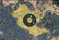
Create a Shape — Telestrate

To create a telestration, select the Telestrate icon. While the Telestration Tool is active, map scrolling is disabled, allowing for free form drawing with a mouse or stylus on the map.
Select the Color Palette icon to open a drop-down palette of colors from which to choose. Once a color is selected, draw upon the map with the left mouse button or stylus. Several lines of various colors can be part of a single telestration. Select Undo to remove the most recent activity.

Select End to end the current telestration session and save all activity as a multi-polyline shape. The entire telestration can be moved by long pressing/right clicking near the center of the telestration and selecting a new location.
Selecting a telestration will open the Radial menu. Options available include: Delete and Details (with quick send from sub-radial). Select Details to change the Name or Height of the telestration, enter Remarks, Change Line Color, Line Style, Delete Lines or Add Lines.
After the telestration has been created, select Send to send the telestration to another user or select Attachments (paperclip) to attach a file(s) to the telestration.
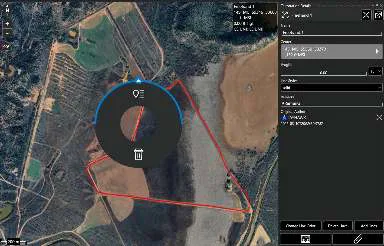
Create a Shape — Manual

To create a manual polyline, select the Manual icon.
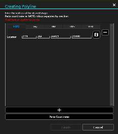
The Creating Polyline window will appear with tabs at the top to choose between the supported coordinate formats. Each coordinate entry represents a point in the polyline. Additional points can be added by selecting the + (Add Coordinates) button at the bottom of the window. If a set of coordinates has been previously copied, selecting Paste Coordinates will add a point for each coordinate entry in the set.
A point can be removed by selecting the - (Remove Coordinate) button that appears beside a coordinate entry. Select Auto-Fill to update a coordinate entry to use the coordinates of the map's center. A minimum of three points are needed to create a manual polyline. Select Finish to plot the polyline on the map.
3D shapes
Closed polylines, circles, rectangles, ellipses and freeform shapes with heights can be rendered as solid 3-dimensional objects when the map is in 3D View. Selecting the clamp option from the radial will clamp/unclamp the shape, allowing it to be viewable while 3D mode is active.
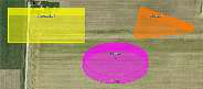
Line Styles
All shape types support four different line styles: solid, dashed, dotted and outlined. These line styles are accessible from a shape's details and are selected using the available drop-down.
GeoFencing

The Geo Fence Tool creates a virtual fence that triggers entry/exit notifications if map items of interest cross the virtual boundary lines. A Geo Fence can be added to any closed Drawing Tool shape (circle, rectangle, closed polygon, ellipse, freeform).
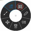
To create a new Geo Fence, select the Geo Fence icon from the radial. The icon will not be highlighted and the tooltip will display "Create Geofence." The Create Geo Fence window will open with options to configure the new Geo Fence. A previously created Geo Fence can be edited from its radial by selecting the Geo Fence icon (the icon will now appear highlighted and a tooltip will display "Edit Geofence"). Selecting the Edit Geo Fence radial option will open the Geo Fence tool which can be edited as needed.
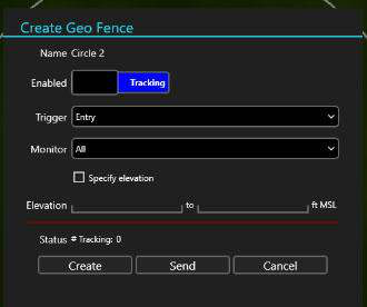
The Enabled Field slider will move to Tracking by default when the Create Geo Fence window is opened. Toggle the slider between Tracking and Off to enable/disable the Geo Fence. Use the Trigger field to define which types of Geo Fence breaches to monitor. Choose between Entry, Exit or Both. Use the Monitor field to define which entities the Geo Fence will track. Choose between TAK Users, Friendly, Reds, Custom or All. Check the Specify Elevation box to enable the Elevation field, where elevation boundaries for the entities being tracked can be defined. Select Create to finish creating the fence. Select Send to send the shape with the active Geo Fence to another user. Select Cancel to close the Create Geo Fence window and discard changes.
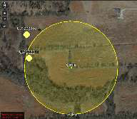
The default radius for monitoring users (filtered within the "Monitor" field) outside the Geo Fence is set at 75 km. This means the total area monitored begins at the farthest point from the center of the shape plus 75 km.
When a Geo Fence breach has been detected, an alert widget will appear in the lower left of the map display and a notification will be listed in the WinTAK notification list. Select the Notifications Flag in the upper right corner of the window to view the notification list, or select the Geo Fences icon in the Toolbar. Geo Fence alerts may be deleted from either location.
Source
WinTAK Software User Manual, Version 5.7, 26 March 2026, pages 59–67.